2×2 LED matrix
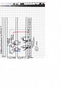
- Breadboard layout for the 2×2 matrix with rows and cols labelled

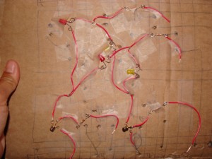
- Laid the circuit out on a cardboard simulation of the breadboard, with wires taking the place of the breadboard rows and columns.
It’s unorthodox, but it helped me to do this to see the flow of the current. I tried to do it from the breadboard, but it was a bit easier for me to understand when I could move the wires around a bit.
I also really like the look of the wires and the components in this “soft” circuit. I guess this could be a really funky sewable electronics project if we wanted it to be! 
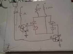
(above) Finally able to decipher what it did, and got Joe the Bro to help explain it.
Note: the 2N2222 transistor is a NPN (not pointing in) BJT (bipolar junction transistor). Collector is negative, base is positive, emitter is negative. Technically, the flow of current is from positive to negative in a diode, but the application of a current to the base AND a current being applied to the collector will enable saturation of the middle layer of the transistor sandwich and permit flow from the collector to the emitter.
Circuit explained.
The two transistors are acting as switches. A voltage applied to the base will cause the base layer to become saturated with electrons and cause the current to flow from the collector to the emitter . This permits a flow of the current through the 2 LEDs connected to each transistor.
Unplugging one of the transistor bases will prevent the related collector-emitter flow, and will turn off those LEDs attached to the transistor.
Disconnecting the wires attached to either of the 220 ohm resistors will break the circuit for the two LEDs connected to that resistor.
Next up: add 4 single input, single output switches on each of the resistors.

